The following factors are affecting the performance of a copper pair and problems are increasing with the higher frequencies involved in ADSL/VDSL. The below conditions, should be tested when delivering a new service or during fault diagnosis.
- Return Loss
- Insertion Loss
- Longitudinal Balance
- Crosstalk
- Noise
- Interruptions
- Split Pairs
- Gauge Changes
- Bridge Taps
- Bad Cable Twisting
Copper Loop Prequalification
Prequalification testing must be able to determine the total length of the line and include standard Metallic loop testing (AC/DC voltages,resistance,capacitance). Some faults will only affect one of the services and some faults will affect all services.Length Loop: Useful piece of information which must be estimated.
Comparisons can be made between initial and new length loop measurement where it can indicate severe problems. If it becomes much shorter a damaged wire can be suspected and If it has grown longer it may indicate water ingression or bad coupling in the copper pair. Length Loop estimates, although not very accurate, could be useful as complement to length estimates achieved using SELT.
AC Voltage: On T-G and R-G expect AC voltage from 0.2-10VAC, more that 50VAC is a safety hazard.
Capacitance/Longitudinal Balance: Acceptable longitudinal balance should be > 60 dB
Measures how well does the circuit reject noise. Only grounded/balanced pairs will limit noise. An unbalanced circuit can cause crosstalk noise, causing slower xDSL transmissions. Root causes of marginal or unacceptable longitudinal balance are:
- DC voltage
- A Tip or Ring ground.
- Open one side on a lateral, open one side on a bridged tap, crossed with a nonworking pair.
- Series resistance.
When the cable pair is free of DC type faults, the capacitive balance T-G and R-G should measure the same length and represented as a %. For 3Play, the capacitive balance should be more than 98% to pass the longitudinal balance test. Corroded contacts act as capacitive faults that especially lead to high attenuation at low frequencies.
DC Voltage: On T-G and R-G acceptable voltage should be 0VDC, on an inactive pair.
Short : Bad bonding and grounding faults < 30 MegOhms affect the longitudinal balance.
Isolation Resistance: For T-R, T-G, and R-G acceptable resistance > 999 MegOhm
Series Resistance:
- Any series resistance will affect the bandwidth services.
- Water/Moisture will cause the resistance to change.
- Corrosion can be detected by passing a current through the pair measuring the resistance in one direction and then the other.
- A corroded joint often has similar properties to a diode, where current will flow one way and not the other or better in one direction than the other.
- Cannot be easily detected with a classic DMM.
DSL Test:
- Downstream/Upstream Rates
- SNR
- Attenuation
- DSL Stats (FEC, CRC errors)
- Band Information (Bits per Tone)
- DSL Graphs (Attenuation Per Tone)
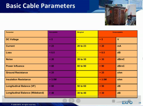
Below the recommended values by JDSU, FLUKE and EXFO respectively


Single Ended Line Test (SELT)
SELT works by transmitting signals on the line and analyzing reflections. It is inaccurate when the line is terminated with a DSL modem. SELT is primarily used for proactive DSL loop pre-qualification as well as for troubleshooting. These tests provide for the loop information on distance,wire gauge, noise, presence of open or short circuits, and estimates of pre-service capacity.SELT testing scenarios:
- Pre-CPE Installation - Test the line for physical bridge and loop taps.
- Pre-CPE Activation - Characterize the loop and measure noise that determines maximum rates.
- Post Activation - If there is a problem, the characterization of the loop can be compared to the results of the pre-CPE activation to see if there are any changes.
SELT tests include:
- Loop Characterization: Distance (in km)
- Loop Characterization: Wire Gauge (in mm)
- Noise Floor (dBm/Hz given per kHz tone frequency)
Dual Ended Line Test (DELT)
Double-Ended Line Testing, is an ADSL diagnostic capability defined in the ADSL2 (ITU-T G.992.3), ADSL2+ (ITU-T G.992.5), VDSL2 (ITU-T G.993.2) standards and others (ITU-T G.997.1 and G.996.2). DELT integrates many of the same capabilities found in precision stand-alone ADSL test equipment into the iMAP and DELT enabled CPE. DELT provides information about the quality of the link and troubleshooting of a DSL channel. Measurements are collected of factors that influence DSL performance such as attainable rate, attenuation, signal-to-noise margin, channel noise and more.DELT results are available in summary form, or in a detailed report file. The summary provides basic information on maximum train rates, overall loop attenuation, and SNR. The detailed report contains several arrays of measurement data which can be converted into plots. All of the information is included in the detailed DELT CSV file. This file contains the following measurement data:
- Upstream/Downstream Attainable Bit Rate (bps)
- Upstream/Downstream Line Attenuation (dB)
- Upstream/Downstream Signal Attenuation (dB)
- Upstream/Downstream SNR Margin (dB)
- an array of Transmit Spectral Shaping values ( TSSi)
- an array of Subcarriers for both upstream and downstream
- an array of SNR Margin values for each DMT subcarrier, SNR(f),
- an array of Bit Allocations for each DMT subcarrier, bi, Range is 0 to 15.
- an array of Gain Allocations for each DMT subcarrier, gi,
- an array of H(f) Real - The real component of the characteristic function.
- an array of H(f) Imaginary - The imaginary component of the characteristic function.
- an array of Hlog(f) logarithmic values of the magnitude of the channel frequency response
- an array of logarithmic values representing the quite line noise, QLN(f).
DELT diagnostics can be used for troubleshooting customer complaints and can be executed in extremely degraded cases where the ADSL link cannot train up.
Of the graphical array data generated by DELT, Bitloading, QLN(f), Hlog(f), and SNR(f) are the most useful for troubleshooting issues with ADSL performance. These graphs can help determine if a problem is caused by noise, outside plant, or the ADSL hardware or configuration.
Bit Allocation (b i): Number of data bits allocated into each subcarrier
Sharp transient drops in bit allocation, can usually be traced to peaks of noise that degrade the channel’s SNR. The exception to this rule is the sharp drop caused by the ADSL Pilot Tone, a single frequency tone used by the ATU-R for timing recovery. Also subcarrier 67 is ADSL pilot tone, it's not noise.
HLog(f) : The frequency response of the channel
It can indicate the presence of certain impairments on physical copper loop like :
- degraded contacts/taps
- capacitive problem causing attenuation in the lower frequencies
Quiet Line Noise - QLN(f): Indicates the noise levels in dBm/Hz over frequency
Measured during modem training phase where no signal is transmitted and only external noise component is present. QLN provides a wideband spectral analysis function, and can be used for analyzing crosstalk or radio frequency interference (RFI). Common noise sources that can be identified by their spectral signature and can degrade DSL services, include RF sources such as AM radio stations (520KHz - 1610KHz), broken power supply (radiating strong REIN) and other telecommunication services (T1/E1, HDSL,ISDN BRI).
Signal-to-noise ratio SNR(f): Ratio between received signal and the received noise
SNR data can show time-dependant changes in crosstalk levels and loop attenuation due to temperature changes or moisture issues.Line Impairments
Wideband(WB) Noise: Acceptable Circuit noise is < 20 dBrncCircuit noise will cause modems/STBs to freezing, and pixelation. Any background signals found on the cable are measured and considered to be noise and/or crosstalk. A quiet terminated noise measurement is the best method for measuring noise. Sources:
- Radio Frequency Interference (RFI), xtalk from other services,etc.
- If Noises is more that 20 dB then pair is unbalanced or PI is too high.
- Noise induced into a pair at frequencies above voiceband (>20 kHz)
- Measure WB PSD noise with filter on an idle pair , look for: RMS noise < -50 dBm
- Look for peaks or high noise floor levels that might be a problem
Crosstalk (xTalk) Noise : Acceptable limits 60 dB.
Near End Crosstalk (NEXT) and Far End Crosstalk (FEXT). Impact is lowering of SNR for DSL, resulting in lower data rates. Sources:
- insufficient cable shielding, unbalanced lines.
- straight wires (rather than twisted pair wire)
- wet pairs
- split pairs
- other transmissions in the same binder group (ISDN, SHDSL, HDSL, T1, E1)
Power Influence(PI): < 80 dBrnC
Currents induced in the cable due to mains supply cables and normally does not affect DSL performance. This is so because for example a 60 Hz will have a 9th harmonic only at 540 Hz that falls below usable ADSL bands. A high PI reading causing DSL problems may in fact have a true problem with high-resistance fault that increases PI, NEXT, FEXT and possibly other noise influence. Root causes :
- bonding / grounding issue
- unacceptable interactive distribution power issues
- combination of the two.
Impulse Noise: SHINE and REIN Impulse Noise
Most damaging type of alien noise. The technician will have to correlate the occurrence of impulse noise hits with external events; this is why it is important to make a note of the environmental conditions.
Other sources: opening/closing of an electric gate, wind moving the overhead cables, crossbars, treadmills, induction motors, lasers, electric fences, xmas tree lights, toasters, elevators, dimmer switches etc.
SHINE (Single High Impulse Noise Event)
Example sources : Drills, Fluorescent Lights
short-duration noise spikes (microseconds), happen at switch-on and cause a DSL line to error severely or lose sync altogether.
REIN (Repetitive Electrical Impulse Noise)
Example sources: Power Supplies, Electric Fences.
These events start at switch on and keep going until the source is switched off.
What to look for: 0 noise hits in 5 minutes, Threshold: ADSL2+ = -33 dBm / VDSL2 = -43 dBm
How to Detect Noise
Use G.INP counters (new DSL standard for data retransmission)Use DSL sync test – loop diagnostics. (CRC/FEC counters)
QLN shows noise level and effect on SNR
Effect of Noise on DSL Metrics
SNR (Signal to Noise Ratio) margin low < 8 dBSNR margin is how much more dB noise can the circuit tolerate and still maintain BER ( bit error rate). Possible issues:
- Degraded signal
- (metallic faults)
- Noise too high
- Bad balance
- Shield degradation/unbonded
- Carriers/xtalk
Line keeps dropping sync. Possible causes:
- Loop too long
- Too much power influence
- Neighbor just got high speed Internet
- VDSL2 from a remote
- impacting CO/exchange-based ADSL
- Impulse noise from premises
CRC (CRC Cyclical Redundancy Check) >5
CRC errors are uncorrectable errors. CRC is an error-detection mechanism only. When more than 5 CRC counts occur over a 15-minute period, the customer may start to experience issues.
Possible causes:
- Cable faults
- Xtalk
- Impulse noise events
FEC (Forward Error Correction) > 200
FEC errors are DSL automatically corrected errors. When more than 200 FEC counts occur in a 15-minute period, data rate may be reduced due to system transmitting/receiving FECs.
Possible causes:
- High resistive fault/series Ω
- Noise/impulse
- Xtalk
References:
http://www.exfo.com/library/multimedia/webinars/testing-fundamentals-wideband-copper-dsl
JDSU: Loop Analysis using DSL Data HLog, QLN, SNR, and BPT
JDSU: xDSL technology update and challenges Test and measurement solutions for DSL voice, data and IPTV services
No comments:
Post a Comment